PCR2 Users Manual
Introduction
PCR2 are bi-directional people counters that use a novel 24 GHz radar transceiver to detect motion from both directions simultaneously. This allows the devices to be mounted parallel to the walking direction. PCR2 detects both directions independently when a certain distance exists between people. Meter readings are transmitted at regular intervals over a public or private LoRaWAN™ network. All parametric sensors are equipped with a USB configuration port for firmware setup and update.
Device types
The PCR2 device family is suitable for indoor and outdoor applications. In addition, various power supply options are available.
All types include a LoRaWAN® 1.0.3 Class A compatible modem supporting LoRaWAN® regions EU868, AS923, AU915, US915. Since firmware V4.0 it is possible to switch LoRaWAN® region on the fly.
| Type | Used for | Power supply |
|---|---|---|
| -IN | Indoor people counting | External 5-12VDC or USB |
| -XIO | Counter with digital outputs For use with industrial controllers |
5-24V DC |
| -OD | Outdoor people counter | External 5-12V DC |
| -ODS | Outdoor people counter | Solar panel |
| -ODA | Outdoor people counter | 110-230VAC |
| -ODB | Outdoor people counter | Exernal Battery Box |
| -ODBS | Outdoor people counter | Exernal Battery Box or Solar panel |
This user manual applies to all device types. Differences are noted accordingly
Configuration
Configuration using PPX
PCR2 devices can be configured by using an USB cable connected to the 'CONFIG' port on the device and using Parametric Product Explorer PPX.
![]()
PPX is a Web-based configuration tool for all Parametric devices. It runs directly in the web browser without installation and on Windows, Mac or mobile phones.
NOTE: USB is not supported on Mobile Phones
Configuration using the CLI
However, it is also possible to communicate directly with the device by using a terminal emulation program. Please see the CLI Documentation for detailed information.
Application Settings
Uplink Mode
PCR2 can be operated in 3 uplink modes. The modes differ in when and how often data is transferred.
Timespan
The device counts all movements during a certain time. After this time has elapsed, the counter readings are transmitted. Duration can be changed with the Interval Setting.
NotZero
Same as Timespan but uplinks are blocked as long as there is no movement. This can be used to save uplinks or energy.
Trigger
Immediately sends an uplink when a movement is detected.
Note: LoRaWAN® Duty Cycle Compliance is respected on all PCR2 devices. This can cause an uplink to be delayed even if trigger mode is enabled.
The Uplink mode can be changed via a LoRaWAN® downlink.
Interval
The interval time is the measurement duration of the device. During this time, movements from the left and right are added up. After the interval time has elapsed, the data is sent to the server (LoRaWAN® Uplink).
Setting range: 1-1440min (1440 min = 1 day)
The Interval setting can be changed via a LoRaWAN® downlink.
Holdoff Time (Filter Time)
Holdoff is used to prevent fast consecutive counts. For example, if Holdoff is set to 10 seconds, no second count will occur for 10s after a count.
This function can be turned off by setting the value to 0
Setting range: 1-600s (0 = off)
The Holdoff timer setting can be changed via a LoRaWAN® downlink.
Sum Up
PCR2 can operate as interval counters or totalizers.
| Sum Up Mode | Uplinks |
|---|---|
| disabled | LTR and RTL represent number of detections since last uplink (interval) |
| enabled | LTR and RTL represent all detections (totalizer). If enabled counters count up to a maximum of 65535 and must be manually reset with a downlink or the CLI |
Sum Up Mode can be enabled/disabled in PPX or via a LoRaWAN® downlink.
Note: We recommend to use interval mode and calculate the sum on the application server since it is more flexible and does not require a downlink to reset the counters.
Radar Settings
Radar settings are used to adapt the device to the environment situation. It is therefore important to set the optimum distance to the moving object correctly. In environments with a lot of background movement, the sensitivity can be adjusted.
Note: The devices are shipped with factory settings, that should be reasonable. It is advisable to only change MinDistance and MaxDistance in the beginning. If counting results are not as expected also change the Sensitivity.
Installation
Mounting location thoughts
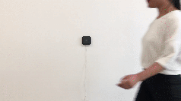
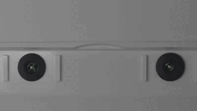
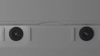
PCR2 are 1D sensors measuring people's movement from two directions along a virtual line. As it cannot look through people, finding the right place is essential to get good results:
Side mounted PCR2
PCR2 devices should be mounted sidewise if possible for best performance.
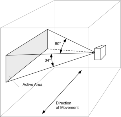
| Installation height: | 1.2-1.4m above ground |
| Direction: | Surface should be parallel to direction of movement |
| Distance between persons: | 40° or more |
Top down mounting
PCR2 could be mounted over head.
Note: Detection wide is reduced to 34° when placed over heads. Minimum distance from sensor to person's head should be more than 0.5m
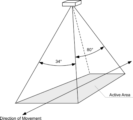
| Installation height: | 0.5-4m above person's head |
| Direction: | Surface should be parallel to direction of movement |
| Distance between persons: | 40° or more |
To increase counting accuracy we strongly recommend avoiding following situations
-
Objects like poles, wall, doorframes in radar field of view (FOV) can generate reflections and reduce measurement performance
-
Moving objects others than people (escalators, ventilators, curtains)
-
People walking side by side
-
Too wide entries will reduce accuracy (lots of side-by-side entries)
Powering the device
Integrated radar technology results in a constant power consumption between 127-160mW. All PCR2 Indoor sensors need to be external powered.
USB powered
Use a USB power supply to power the PCR2 device by connecting the Micro-USB plug to the "CONFIG" socket.
Note: Use a power supply with low power output. Big power supplies tend to oscillate when there is a very small load.
DC powered
Alternatively you can power PCR2 devices by using a 5-12V DC constant voltage power supply connected to the terminals "POWER".
Initial Setup
We recommend using Parametric Product Explorer PPX initial configuration of your device.
You find the download link in the Document section of our website.
Once installed and connected to your PCR2 you see following screen.

-
Change your settings on the right panel
-
Press the "Save" button to write changes to the device
LoRaWAN® Connection
Radar Settings
--
Operation
Device startup sequence
After switching on the device, following sequence will start.
-
Initialization of Radar Processor. LEDs are constantly on.
-
Start Join-Procedure (only if LoRa Modem is enabled). LEDs are blinking slowly
-
After receiving Join Accept, the device switches sends the Configuration Payload on port 190
Detection mode
-
LEDs are off and are quickly flashing if a object gets detected.
-
After Interval time is up, the device sends the PCR2 Application Payload on port 14. This can be done in Confirmed or Unconfirmed Mode.
-
In Confirmed mode LEDs are on until successful received a ACK. After receiving the ACK LTR and RTL counters will be reset. If the device operated in Unconfirmed Mode counters will be immediately reset after sending w/o waiting for an ACK.
LED Signalization
Hardware initialization
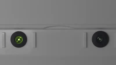
Left LED is blinking slowly during hardware initialization.
Joining LoRaWAN® network
Boths LEDs blinking slowly during LoRaWAN® Join procedure.
LoRaWAN® Timeout
Both LEDs blinking fast if join or uplink ACK has not been received. Device retries in about 1min and retries n attempts.
Check LoRaWAN® keys. The device could also be too far away from a LoRaWAN® gateway.
Inactivity Timeout
The inactivity timeout can be used to automatically reset sum counters (RTL_SUM and LTR_SUM) if there is no movement for a certain time. This is useful if absolute counting of persons is used and one would like to start with zero in the morning. Inactivity Limit can be enabled by setting the value to zero.
LinkCheck Intervals
There are several reasons why an end device could land in a stranded state where it does not receive any downlink messages from the network, including:
-
The device transitioned quickly between two gateways with channel maps that don’t overlap
-
The device’s RX1 and RX2 reception parameters become out of sync with the network server
-
The device roamed to a different network provider’s region (if there is no roaming agreement between those two providers)
PCR2 devices using the Link Check Request/Answer mac command for detecting if there is still a connection to a Gateway.